Thanks to Ron Pommerel at RPS Engineering for calculating the location of the upper and lower positions for the pivots on the front uprights. I then could machine the uprights to take the wheel bearings for the spindles, the mounts for the brake calipers as well as the mounts for the pivots. Then the brake rotors need to be mounted, so an aluminum spindle needed to be machined to mount the brake rotor in the correct location and also to allow for clearance of the calipers inside the road wheels. The photos show the front brake rotor and spindle assembled on the upright.
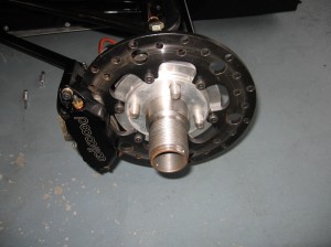
Front RHS upright with brakes fitted
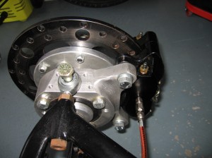
Front RHS upright with brakes fitted side view
To add more complication to the build of this project the OZ-Racing rims have a center retaining lock nut design, so I had to also machine up steel carrier spindles with left & right hand threads to mount a large retaining nuts.
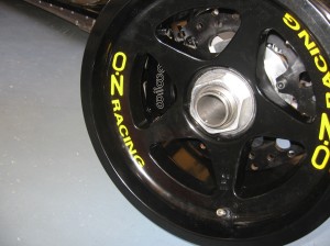
Front Road Wheel and brakes assembled onto the upright
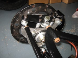
Front RHS upright with brakes and steering arm fitted
The rear uprights also needed to be machined to fit the wheel bearings and also allow for the drive shafts, and the rear brake calipers need to be mounted. The rear drive shafts that I ended up deciding on are out of an Alfa V6, as they have the same bolt mounting as a Holden Commodore IRS shaft but the Alfa shafts are about 50mm shorter than the Commodore. This allowed me to get the correct rear Track due to the large off-set on the OZ-Racing rims.
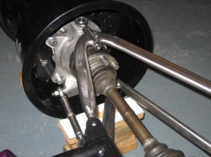
RHS Rear upright with brakes and drive shaft fitted
The photo shows the Rear RHS upright assembled with the rim, brake rotor, brake caliper and drive shaft. Note the drive shaft bolts and control arms are just dummy’s to allow me to check the clearances on the rims etc.