The Suspension development starts on the Rotary Hillclimb Racing Project.
The next major hurdle is the suspension and how to make the geometry from the design that Van-dieman has set out on the front suspension and then apply this to the rear suspension. But to do this I needed to get a few major things like, up-rights, road wheels, brake rotors and brake calipers.

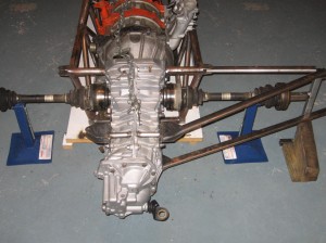
Rear Suspension Pickup Points
The front and rear up-rights need to hold the road wheels and the brake rotors and all of this had to fit inside the road wheels as well as being in the correct positions to accommodate all of the suspension points. Again cost was the driving force behind my decision so I purchased 4 bare aluminum up-right castings from Pro-sport Developments. These would have to be machined to take the front wheel bearings and the rear drive shafts etc.

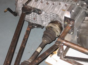
Rear Suspension RHS pick up points
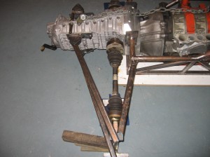
The photos show the approx locations of the rear suspension pick-up points and the drive shafts angles etc. Note the rear position of the control arms are to be bolted to the gearbox housing. I will be using the rear half of the gearbox as a stressed member to help save weight.
I also would need road wheels to be able to calculate the suspension information so I purchased some ex-formula Holden one piece OZ-racing magnesium rims the fronts are 10″ wide x 13″ ID and the rears are 14-1/2″ wide x 13″ ID. I also purchased some Willwood 4-piston calipers and disc rotors all of these components I needed to get the suspension design correct.

Rear Suspeion pick up point RHS as viewed fom outside
During this process I started to need help with the rear suspension design so I asked Ron Pommerel at RPS Engineering at Brendale for his knowledge of race car design to help me with calculating the roll centers and to work out the suspension pick up points for all the new suspension components.

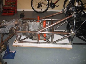
Rear Chassis & Suspension pick up point