Now that the suspension up-rights have been machined and are finished, I now needed to link the uprights to the chassis and be able to connect the suspension components to the car. As the front suspension is relatively fixed, thanks to Van-dieman, the front was the first suspension control arms that I made. The photos show the front RHS upright with the upper and lower control arms attached note that the upper camber adjuster is just tacked together to check to see if there is any issues with clearance etc.
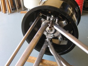
Front RHS Upright with Control Arms tacked together
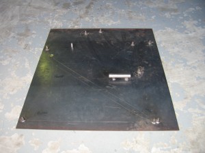
Jig for Control Arms
To make the arms I made a jig out of 3mm steel plate and plotted out the sizes of the arms to scale and then cut and bent oval tube to fabricate the control arms. I planned to have 6 degrees of positive caster in the front so to achieve this I just simply off-set the upper and lower pivots on the jig when making the arms. It took me 3 proto-types to get the finished arms that are shown in the photos, due to the rim off-set as the rims hit the control arms on full lock.
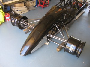
Front Suspension Arms on Chassis
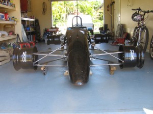
Front Suspension Arms on Chassis Front View
The rear suspension was the next to do and as per the front I set out the sizes on the 3mm steel plate and went about fabricate the control arms as well as the toe control arms and also the camber adjusters. The photo show the rear suspension with the arms bolted to the chassis and the control arms.
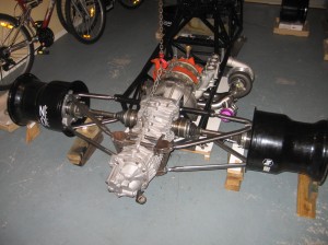
Rear Suspension View